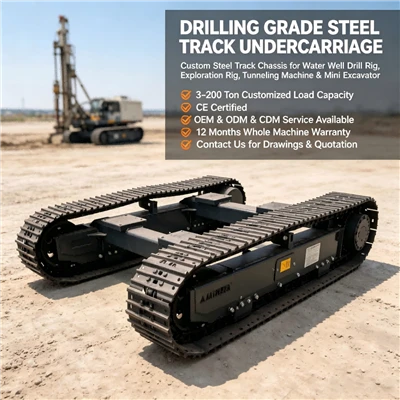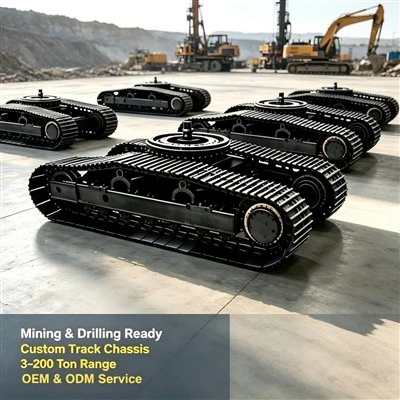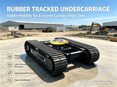

Tracked travel mechanisms are widely used in construction machinery, tractors, and other field vehicles. Harsh travel conditions require the travel mechanism to possess sufficient strength and rigidity, as well as good traveling and steering capabilities. The tracks are in contact with the ground, while the drive wheels are not. When the motor drives the drive wheels to rotate, the drive wheels, under the driving torque of the reducer, continuously roll the tracks from the rear through the meshing of the teeth on the drive wheels and the track chain. The track in contact with the ground exerts a backward force on the ground, while the ground correspondingly exerts a forward reaction force on the tracks. This reaction force is the driving force that propels the machine forward. When the driving force is sufficient to overcome the travel resistance, the support rollers roll forward on the track surface, thus moving the machine forward. The front and rear tracks of the entire tracked travel mechanism can be steered independently, resulting in a smaller turning radius.
The tracked travel device consists of "four wheels and one track" (drive wheel, support roller, guide roller, tow roller, and track), a tensioning device, and a buffer spring, forming the travel mechanism.
Tracks are flexible chains driven by the drive sprocket and surrounding the drive sprocket, road sprocket, idler sprocket, and track carrier sprocket. Tracks consist of track plates and track pins. The track pins connect the track plates to form the track chain. The track plates have holes at both ends for engagement with the drive sprocket and idler teeth in the middle to adjust the track and prevent it from slipping off when the tank turns or tilts. The side in contact with the ground has reinforcing ribs (patterns) to improve the track plate's rigidity and traction.
Tracks operate under harsh conditions and must possess sufficient strength and rigidity, good wear resistance, and be lightweight to reduce metal consumption and dynamic load during operation. They must also have good traction to ensure sufficient traction while minimizing drag during travel and steering.
Drive Wheels
In tracked machinery, drive wheels are mostly located at the rear. This arrangement has the advantages of shortening the length of the track drive section, reducing friction loss at the track pins due to driving force, extending track life, and preventing track arching, thus avoiding the risk of track slippage during turning and improving the efficiency of the running gear. The center height of the drive wheels should help lower the center of gravity (or vehicle height) and increase the track contact length, improving traction; therefore, the drive wheel height should be as small as possible.
Train Track Rollers
The function of track track rollers is to support the track, preventing excessive track sagging, reducing track vibration during movement, and preventing lateral slippage. Track track rollers are similar to support rollers, but they bear less load and have better working conditions, so their size is smaller.
Tensioning Device
The main function of the tensioning device is to tension the track and prevent track slippage.
The buffer spring of the tensioning device must have a certain preload to generate pre-tension force in the track. Its function is to prevent the track pins from loosening easily due to slight external force during forward movement, thus ensuring proper engagement between the track pins and drive wheel teeth. During reverse movement, it generates sufficient traction to guarantee normal engagement between the track pins and drive wheel teeth.
The tension spring, due to the recoil effect of the device, pushes against the guide wheel on the right, maintaining a certain tension during operation, thereby guiding the track tension guide wheel.
The buffer spring's main function is to work with the tensioning device to achieve elastic tension on the track. Since the tensioning device achieves tension by pushing the guide wheel with the spring, compression or tension springs are sufficient.
The guide wheel's position depends on the drive wheel's location, usually at the front. The guide wheel guides the track's correct rotation, preventing deviation and off-tracking. The center height of the guide wheel above the ground should help lower the center of gravity.
The track roller is one of the four wheels and one track components of a tracked construction machinery chassis. Its main function is to support the weight of excavators and bulldozers, allowing the tracks to move along the rollers. The number and arrangement of track rollers should facilitate a uniform distribution of track ground pressure. Agricultural walking mechanisms often operate in mountainous or hilly areas where roads are mostly unpaved. Tracked systems require a low average ground pressure, and the pressure on the track rollers must be evenly distributed.
The walking mechanism mainly consists of the tracked chassis body, which serves as the platform for the aforementioned components, facilitating the fixing and installation of guide wheels, track rollers, etc.